For the full article please see the January issue of PC Plus Magazine. If you want to add a cool new capability to your robot, thermal tracking should be at the top of your list. Using this system you can create a heat seeking autonomous robot that will follow you around the house like the family pet. But “follow me” applications are not the only use of this flexible tracking system. By equipping it with a night vision IR video camera you can use it as a mobile or standalone security monitoring system able to catch and track any warm-blooded animal that may be lurking in the dark.
As you will see, the Thermal Tracking System is a self contained programmable thermal sensor that you can easily incorporate into your robot project. Integration to your robot is through two connections. The first connection is for the serial interface and the second is for power. Through the serial interface your robot will send commands to activate the tracking system. It can also access thermal data such as direction and temperature of the heat source.
The Devantech TPA81 Thermal Sensor is the heart of the Thermal Tracking System. This sensor has an array of eight heat detectors (called pixels) mounted horizontally giving it a field of view of about 45 degrees. The TPA81 uses a synchronous interface bus called I2C. Over the I2C Bus, the tracking software polls the eight heat registers and determines the direction of the heat source.
Like many of my projects, the brain of the Thermal Tracker is the Propeller Chip from Parallax. The Propeller is actually eight individual microcontrollers called Cogs built into one chip. The Propeller can be programmed in a ‘C’ like high level language called Spin.
The Thermal Tracking System optionally uses an infrared wireless colour video camera. The camera used is manufactured by SecurityMan and was obtained from Smarthome (#76004). This camera can transmit a standard video composite signal directly to a television or DVR/VCR up to 300 feet.
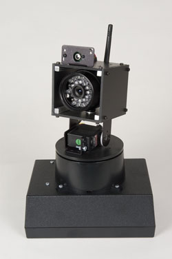
The thermal sensor and camera are mounted on servo pan and tilt system. This system is constructed by combining a Pan and Tilt Kit and Base Rotate Kit available from Lynxmotion. The Base Rotate Kit adds needed stability to the Pan and Tilt Kit for heavier load of the video camera. This combination allows the camera to be panned 180 degrees left to right and about 90 degrees up and down. Mounted on top of the tilt bracket is a custom enclosure used to mount the video camera and TPA thermal sensor. It was constructed using four 3 inch aluminum square bars and some PVC stock. It measures approximately 3 x 3 x 3 inches.
The robot sends commands to the Thermal Tracking System using a simple request/response protocol. All commands (and responses) have the same header that starts with an ASCII exclamation (!) character followed by one byte that contains the length of the message.
Here is an example of the three byte Halt command:
33 01 05
! = ASCII code for an “!”
1 = Length of message – in this case only one byte follows
5 = Message – the Halt command code
Most of the Thermal Tracker related components are mounted in or on a Serpac 173-BK Enclosure available from Jameco Electronics. The tilt and pan system is located on the top of the case and all the electronic components are placed inside. Connectors for the serial interface and power are mounted on the back of the enclosure.
The Parallax Propeller Proto Board was used to simplify the use of the Propeller Chip. It contains all the support hardware needed for the Propeller. This includes power supply, EEPROM, 5 MHz crystal, and programming connector. All the Propeller I/O pins are easily accessible using this board. All the wiring was done with wire-wrap. Since the circuit is relatively simple, direct point to point solder wiring could also have been used.
|
 Robots with a Mission